
Guide to weld inspection
This guide is intended for pipeline engineers, welders, weld inspectors and managers. It covers the history and role of welding in the oil and gas sector, the most common types of welding, the importance of inspection, weld inspection methods and the role of a weld inspector. It also contains links to more detailed page resources. Scroll down for more or prefer to read offline? Fill in the form below and we will send you a PDF copy.
Updated: March 2023
Page contents:
Introduction to pipe welding
TWI Global
Welding is the process of joining metals together with heat. Modern methods usually require four main components – the metals, a heat source, a filler material (sometimes referred to as a consumable) and a shield from the air.
The concept has been around since the Iron Age, when blacksmiths invented ‘forge’ welding, a solid-state process where two pieces of metal are heated and then hammered together until they fuse. From 1800 numerous scientific breakthroughs led to welding advances such as experiments in arc production, the discovery of oxyacetylene and the invention of resistance welding.
During the late 19th century and early to mid-20th century, growing railways, rapid industrialisation, increasing oil and gas production and the manufacturing demands of two world wars led to many improvements in welding techniques and the discovery of numerous new methods.

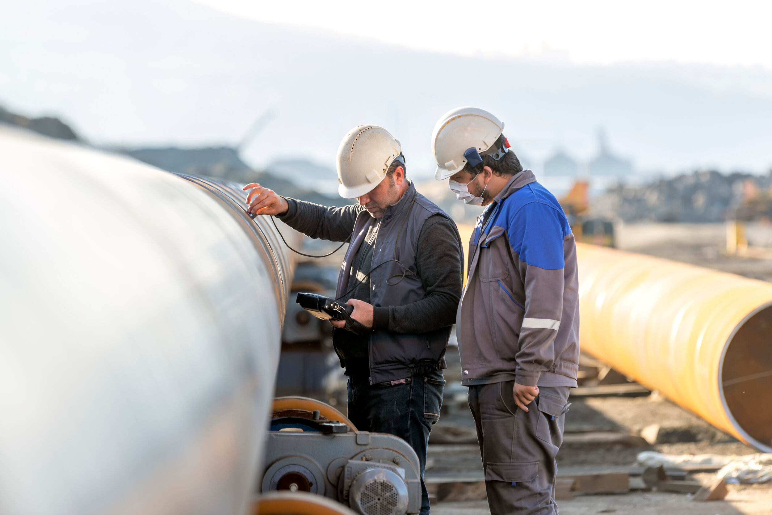
OMS weld inspection system in action offshore
Today there are many welding techniques in use, each ideal for its particular industrial niche and methods for joining many different kinds of metal. From precision laser welding used in the aerospace industry to basic stick welding taught to beginners at the start of their career, welding is a vital part of industrial processes all over the world. Automatic welding is now common, either carried out entirely by robot or with some human involvement to prepare materials.
Welding in the oil and gas industry

Pipeline across a desert
The importance of welding in the oil and gas industry cannot be overstated. Every stage of production depends entirely on welds, which create and join essential structures that must be robust, durable and stable. The industry has a wide range of welding requirements, from small diameter pipes to enormous rigs and platforms.
There is a distinct correlation between the quality of pipe welds and the performance of a pipeline. Higher quality welds result from good pipe end alignment - leading to improved pipeline performance. For more information about pipe measurement and alignment read our guide here.

Pipes being manufactured
Upstream, midstream and downstream
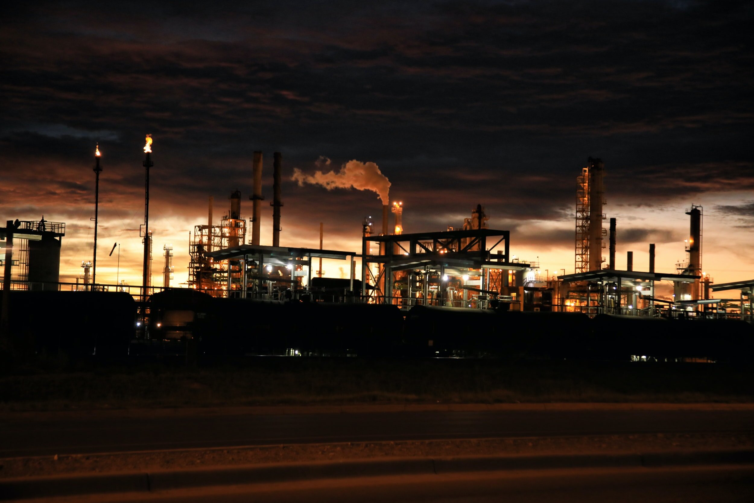
Production of oil and gas is divided into three sections – upstream, midstream and downstream. Upstream is the exploration, discovery and production stage – sometimes called ‘exploration and production’ or ‘E&P’ where new oil deposits and gas fields are located, tested and wells are installed. Midstream involves the transportation and storage of crude oil via pipelines, barges and tanks before it is refined. The downstream sector is where crude oil and natural gas is refined and purified before being distributed for commercial use.
Welding in the upstream sector involves the creation of large, high-strength edifices to support production operations, often in harsh environments or under the sea. In the downstream sector, welding is used to create and maintain the complex systems of pipes, furnaces, pressure vessels and supporting structures required for refining. Upstream production involves the creation and installation of unbreakable pipelines through which crude oil and natural gas travel and tanks in which it must be stored before refining takes place.

Pipes in a stack
Quality, speed and efficiency
Successful energy projects are dependent on weld quality. Welds must be strong enough to withstand the high pressures, toxic chemicals, extreme temperatures and difficult environments of energy production – and must be robust enough to last for many years.
They must also adhere to stringent safety standards – because the consequences of a weld failure can be catastrophic to safety, the environment, profits and reputation.
To maximise oil and gas production welding must be carried out at speed, with safety maintained at all times. Speed is particularly important during the repair and maintenance cycle where equipment downtime comes with enormous costs. Operators can achieve rapid, safe and robust welding by hiring highly skilled professionals and using the right equipment.
Increasing efficiency through automation
Automation in the oil and gas industry has been increasing steadily, where it can help operators grow productivity, improve safety and raise profits. Welding in oil and gas has not been replaced by the entirely robotised production lines seen in the automotive industry, but many processes can now be carried out by machines with human input, increasing efficiency by up to 40% in some cases.
Common types of welding used in oil and gas pipelines
Welded pipes must withstand the weight and pressure of the fluid that they carry as well as the external conditions where the pipeline is situated. The increased strength of the pipes makes welding a challenge for engineers that have to work with them. To increase reliability and profitability in this industry, effective welding techniques are needed for these materials.
There are a number of pipe welding techniques, including:
Manual metal arc welding (MMAW)
Shielded metal arc welding (SMAW)
Gas metal arc welding (GMAW)
Automatic welding
The best pipe welding procedure depends on the choice of pipe, how it will be used within the pipeline and its intended location. For example, the SMAW welding process is generally preferred for offshore arc welding as it is more suitable for joining longer pipe sections prior to laying. These welds must be capable of withstanding intense production and extreme conditions, especially where water depths run into thousands of feet. Whereas utility pipe networks such as sewers require a far less stringent welding process.
Weather conditions can also affect the choice of weld, with extreme heat in desert conditions and sub-zero temperatures in other zones. Pipe welding is a critical stage in the construction of a pipeline network, with poor welds potentially leading to poor performance or worse, pipeline failures and spills.
MMA/SMAW/stick welding/flux shielded arc welding
Manual metal arc welding, also known as stick welding, shielded arc welding or flux shielded arc welding was invented in the late 19th century. The arc is struck between an electrode flux coated metal rod and the work piece, which both heat to form the weld. As the rod and workpiece heat up, the flux coating melts simultaneously to form gas and slag which protects the weld from the atmosphere. After the run is complete, the solidified slag must be removed from the weld bead.
MMA welding has many benefits – the equipment required is affordable and easy to transport, an external gas source is not required and it is an easier skill to acquire so more people are available for work. It also has disadvantages – the electrode rod must be replaced frequently, which means that only short weld runs can take place. Weld penetration is low, more waste is produced, slag must be removed post weld run and the quality of the finish depends entirely on the welder’s skill.

Metal inert gas (MIG)/gas metal arc (GMAW) welding
In metal inert gas (MIG) welding a continuous solid wire electrode and a shielding gas are sent through a welding gun into the weld pool, melting the base metals and forming the join. As the wire is fed from a reel, the welder moves the torch along the joint line. The shielding gas, usually a mixture of carbon, oxygen and CO2, forms the arc plasma, protects the weld from air contamination and helps reduce spatter by transferring molten droplets to the weld pool.
A versatile technique with many applications, MIG welding is fast and its continuous electrode feed allows long weld passes, reducing the number of passes necessary and increasing productivity. It is fairly clean, creating little waste, and is suitable for various different metals. Disadvantages include the higher level of preparation required and the more expensive, less portable equipment needed. The external gas source means welding is more difficult to control outside the workshop, where conditions such as wind can cause problems.
Pipes being connected
Tungsten inert gas (TIG) welding
Tungsten inert gas (TIG) welding is a form of arc welding used particularly in applications where high quality and precision is required. The welding arc is formed between a non-consumable tungsten electrode and shielded by inert gas. If filler metal is required it must be added separately to the weld pool.
TIG welding produces high quality, clean welds and can be used on the widest range of metals. It is particularly suitable for difficult welds such as those in curved or S-shaped workpieces, and in applications where the weld must have a high quality finish. TIG welding delivers clean, attractive welds with low smoke and less spatter. Welds require little finishing and are strong, ductile and corrosion resistant.
TIG welding is a slower process than some other welding methods and requires a very high level of skill. Like MIG welding it can be extremely difficult to carry out away from a controlled workshop environment.
Automatic welding
From mechanised welding, where parameters may be varied manually, to robotic welding, where sophisticated robot arms perform complex operations across multiple axes, the term ‘automatic welding’ covers a wide range of options, but generally refers to any welding that is carried out by machines controlled by electronic processes.
Automatic welding has the potential to increase productivity and profitability significantly by speeding up the welding process, improving weld quality and reducing both human error and labour costs. It can improve weld integrity and repeatability, capable of producing a better weld than any human welder and allowing almost instant quality control. However, as it is much less flexible than manual welding, automatic welding is not suitable for every application. It also requires a high level of initial investment and an extensive preventative maintenance schedule.

Automatic welding in a car production line
The purpose of weld inspection
“Weld failures are not just accidents or acts of God. Weld failures are the result of human errors originating from unrealistic delivery schedules, oversight, carelessness, ignorance or greed.” Weld Failures, Dr. Jesse A. Grantham, The Welding Leader
Inspecting welds determines whether they are suitable for their intended purpose. Inspectors carry out a series of QC checks to verify that the weld meets design standards and to look for defects or weaknesses. If any problems are found these can be remedied or removed prior to installation.
Inspectors are skilled professionals who are highly trained in welding processes. They compare weld features, such as dimensions, appearance and location, against an agreed set of criteria. Over the years many welding codes and standards have been developed by organisations such as TWI, AWS, ISO and BSI, each specific to a particular industry or weld function. Inspectors use these standards to assess a weld and determine whether it is fit-for-purpose.
Carrying out weld inspection prior to pipeline installation is particularly vital for the oil and gas industry. Weak or defective welds can be spotted and remedied at an early stage, saving time and money. It also helps to protect workers and the environment against the potentially catastrophic consequences of weld failure, mitigating overall risk.

What does good welding look like?
Although different techniques produce different-looking welds, in general a good weld should have:
A smooth and uniform appearance
Good penetration
The correct profile (either flat, convex or concave, depending on the type of weld)
Little to no ‘spatter’
Some colouration of the parent metal either side of the weld
No surface pores
No colouration on the surface
No burns
Even and well-feathered ripples
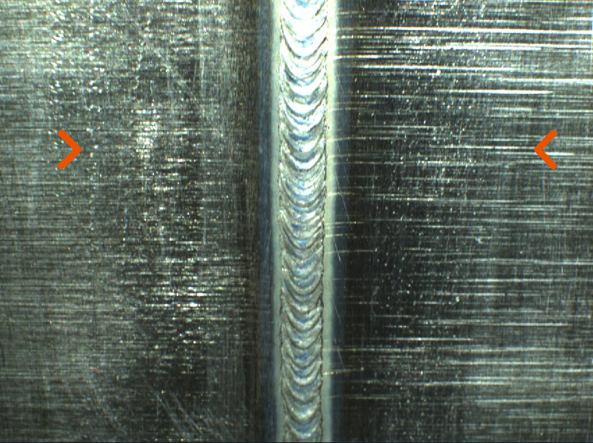
Good weld
A bad weld may have:
Cracks
Overlap
Undercut
Visible lack of fusion
Spatter
Burns
Globules of metal
Erratic weld bead
Inspection as a way of confirming good welds and meeting pipeline standards
Weld inspection is a vital stage of the pipeline installation process. To ensure optimum safety, all welds must be inspected with a variety of methods to assess all features and determine whether acceptance criteria have been achieved.
Welding and the environment
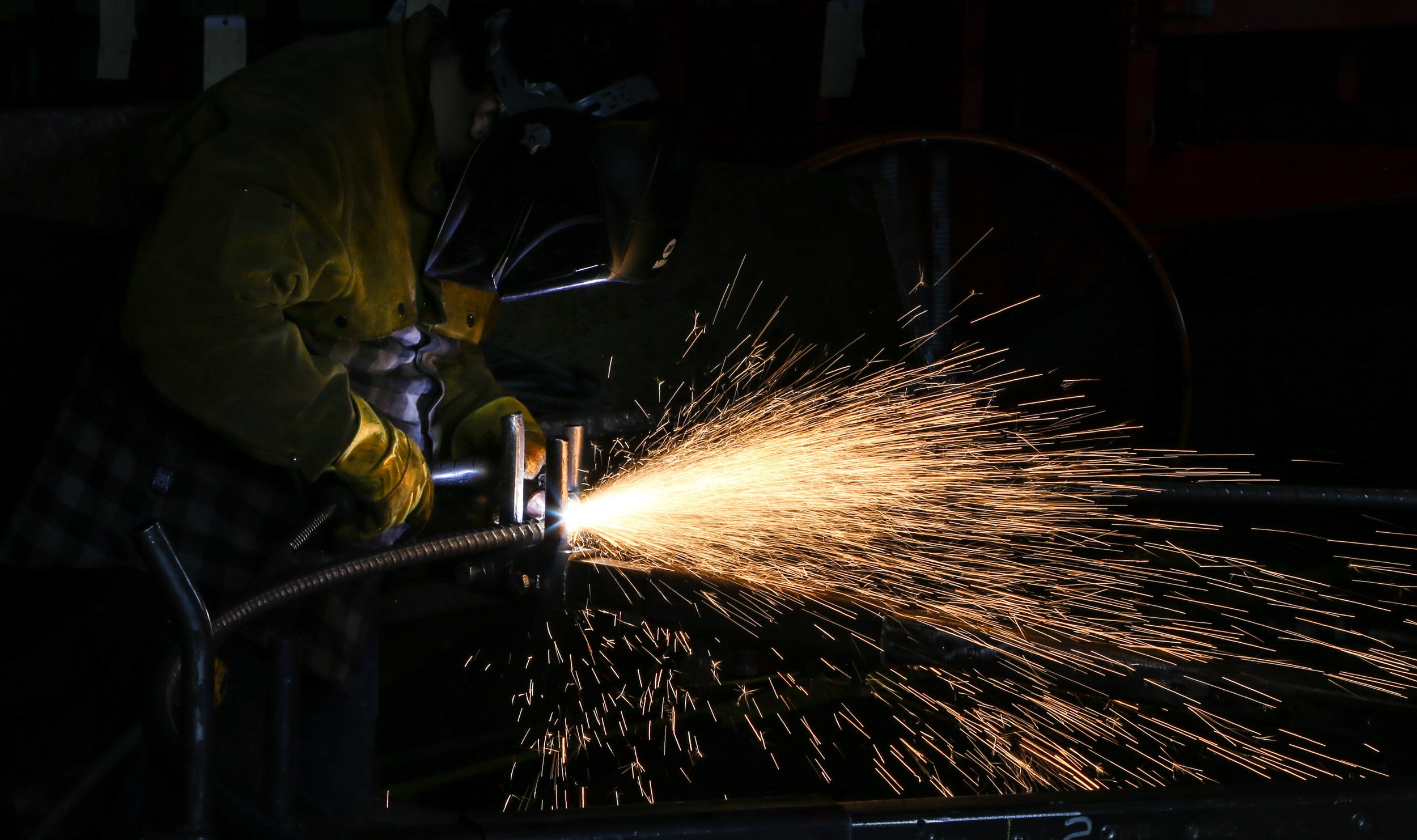
Welding can have a serious impact on the environment. As a high-heat process, welding requires a large amount of energy. TIG welding arcs, for example, can reach temperatures of up to 3,300°C, adding considerable heat back into the atmosphere. During welding toxic fumes such as ozone, carbon monoxide and nitrous oxides, are created, causing air pollution.

Health and safety in welding
High heats, naked flames, toxic gases and electricity means welding can be a dangerous process. To mitigate the risks, industrial welders must be highly trained with skills up-to-date and equipped with the correct personal protective equipment (PPE). Employers must undertake full risk assessments to ensure working practices are in line with expectations.
Reducing the environmental impact
Welding operators can take several steps to reduce the negative impacts on the environment. Where it is possible, TIG welding is the most precise form of welding and creates lower fumes, so can be the best choice. Where other forms of welding are required, welders can use the lowest effective amperage, can choose a less polluting gas mix, can recycle scrap metal and can prepare surfaces thoroughly prior to welding, ensuring paints, solvents and contaminants have been removed. Some welding courses reduce environmental impacts by training welders using virtual reality (VR).
Consequences of weld failure
Every weld in a pipeline is a critical link on which the system depends. If a weld fails, the consequences can be catastrophic for the environment, and for the operator’s bottom line and reputation. Environmental disasters thought to have been caused by weld failure include the collapse of the Alexander L Kielland semi-submersible oil rig in 1980, which killed 123 people, and the San Bruno gas pipeline explosion in 2010, in which 8 people lost their lives.
Weld defects can occur for several reasons – using the wrong materials for the job, applying the incorrect process, welding under difficult conditions or an inexperienced or unskilled welder. Even when welds are successful, they will become worn over time and will require inspection throughout their life cycle.
‘Fatigue failure’ – where small cracks form and spread on a welded structure due to the continued application of stress – can happen in a short time and is a particularly high risk for welds in critical structures such as pipeline risers and stalk tie-ins.
The most common welding defects
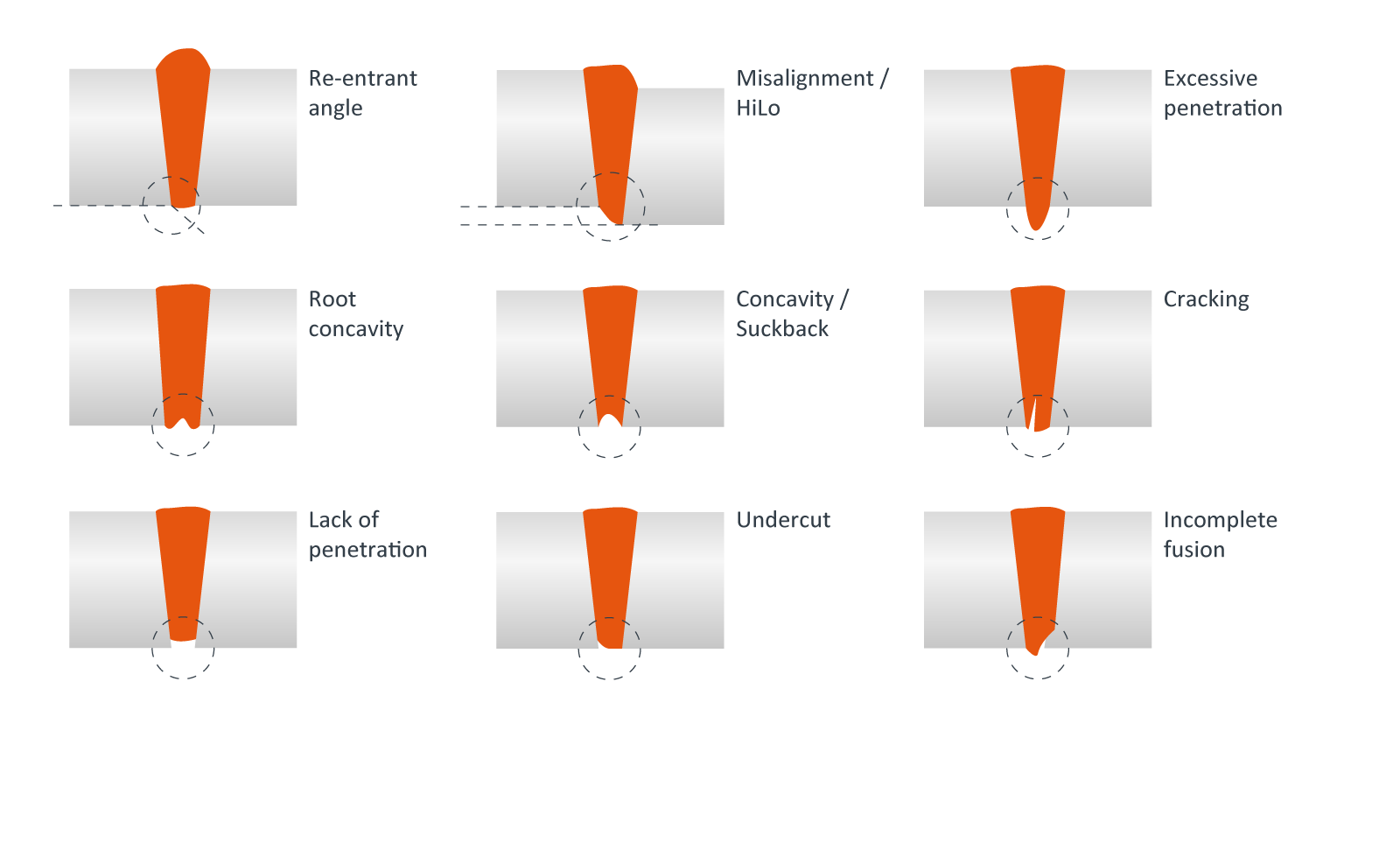
Weld defects
All defects have the potential to cause serious problems in pipeline integrity - these are some of the most common.
Cracking is the most serious defect and will eventually cause the weld to fail. Cracks happen because welds are under constant internal stress, which sometimes exceeds the strength of the base metal, the weld metal or both. Hot cracks occur at temperatures over 1000°C, usually caused by contamination or issues with materials. Cold cracks occur as the weld is cooling, usually as a result of hydrogen diffusion. Crater cracks happen when the weld pool does not have enough volume. Contractors go to great lengths to avoid cracks because the effects are so undesirable.
Corrosion is the unintentional deterioration of a metal caused by reaction with its environment. Almost all environments cause metal to corrode, particularly in the energy industry where conditions are difficult. In welds, consequences are severe – corrosion can cause pipeline failure, leaks, reduced production through closedowns or limited flow - plus the risk of ecological damage and resulting costs.
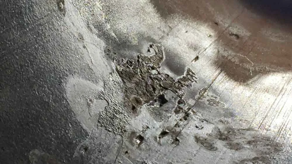
Corrosion on a pipe wall
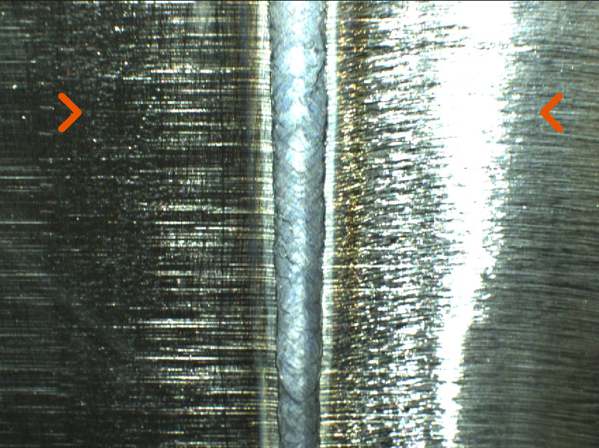
Misalignment (HiLo) refers to the difference between the internal and/or external height of two pipes. Poor alignment causes a weaker weld less able to cope under high fatigue conditions.

Weld showing poor alignment (HiLo)
Excessive penetration occurs when too much weld metal protrudes through the weld root. It is usually caused when a joint gap is too large, root faces are too small, or the heat input is too high. Excessive penetration can cause erosion and/or corrosion.
Root concavity/concavity/suck-back cause a shallow groove to appear in the weld root when the pool shrinks within the weld as it cools.
Weld showing concavity
Lack of penetration/incomplete fusion/undercut is where the weld has failed to fuse to one or both sides of the root, or a shallow groove has appeared in the base metal near the weld root. These types of weld defects are more common in consumable electrode processes such as MIG welding.

Weld showing lack of penetration
Porosity occurs as a result of weld metal contamination and creates a bubble-filled weld that weakens over time.
Slag inclusion – where non-metallic particles of slag (a vitreous material by-product of some types of welding) are trapped in the weld – is usually caused by failure to clean and prepare materials properly, a weld speed that is too fast or an incorrect welding angle.
Spatter – when small particles of molten metal fly out and attach themselves to surrounding surfaces – cannot be completely eliminated from GMAW/MIG welding but can be reduced by improved welding technique and better preparation.
Repairing weld defects
Some weld defects can be repaired, allowing a pipeline to be cleared for use. There are various repair methods available, including grinding, steel or composite reinforcement sleeves, hot tapping and cut-outs. Although repair is possible when a pipeline is already in service, this is usually very difficult and expensive. Solving weld defects is easier and more effective before a pipeline is laid.
Solving defects with grinding
Grinding welds is the most widely used and effective repair method but must be carried out before the pipeline goes into service. It involves applying abrasive pressure to remove excess material using a grinding device such as an angle grinder, flap disc or grinding belt. If carried out correctly, post-weld grinding can improve the weld’s strength. Defects such as excess penetration and spatter can be removed and the resulting smooth surfaces provide less opportunity for corrosion to take hold, while allowing smooth progression of cables or pipeline contents. Welds can be shaped to improve their coatability. Grinding welds with systems such as OMS SmartGrind [link] can ensure they meet design specifications, thus allowing projects to proceed efficiently.
Post-repair checks
Once a weld has been repaired it must be inspected again to ensure it meets design specifications. NDT methods must be used to confirm that the weld is in good condition with no loss of parent material and that the pipe’s wall thickness remains at the specified level.
Reducing the likelihood of weld failure
There are a number of steps operators can take to reduce the chance of weld failure. These include ensuring welds are designed effectively for the project purpose, and that the design is then followed and implemented correctly, choosing the best type of welding for the application, following proper welding procedures and employing highly skilled welders.

How are pipeline welds inspected?
What information is collected during weld inspection?
During the weld inspection process, information, usually in the form of pictures, videos and/or statistics, is collected that identifies defects such as cracks, corrosion, lack of fusion, undercutting, slag inclusion, erosion, porosity and more.
Data fed back by various inspection methods indicates weld appearance and strength, and quantifies defects, showing their size, shape and location. It is used by weld inspectors to pass or fail a weld in the field, to demonstrate that a weld has met project specifications and for failure analysis when something has gone wrong or exceeded tolerances.
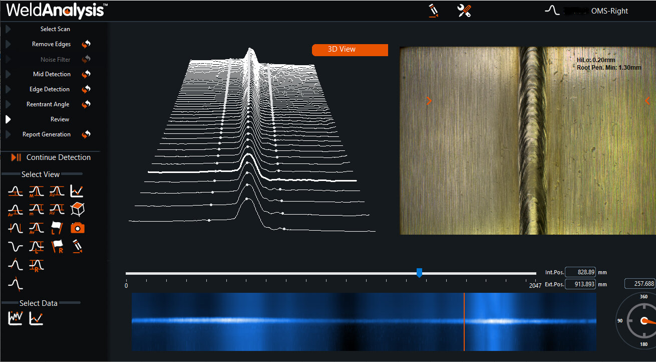
OMS WeldAnalysis software
NDT inspection
In weld inspection, non-destructive testing (NDT) refers to analysis techniques that assess a weld without damaging it. NDT methods are commonly used to examine welds because they can identify and quantify damage such as cracks, corrosion and porosity without causing harm, and can evaluate welds even while they are in service. There are various NDT techniques available, each with its own advantages and limitations. We have described some of the most frequently used below.
Visual weld inspection
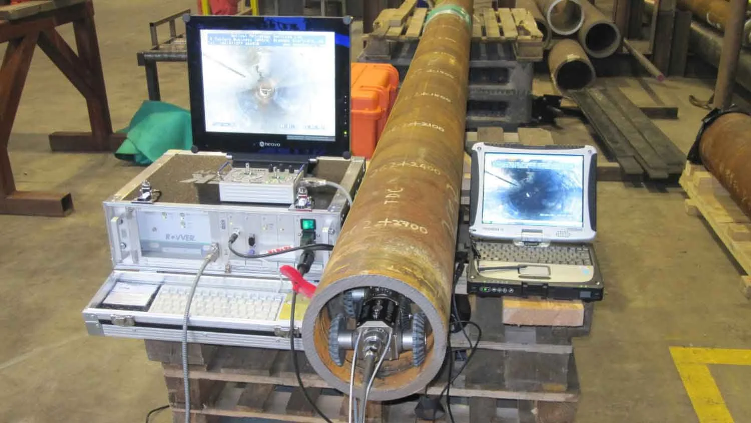
Visual pipe inspection using a robotic crawler
Non-destructive, simple, inexpensive, environmentally friendly and portable, visual inspection is the most common way to assess a weld. Performed using the naked eye, sometimes with the assistance of magnification, visual inspection is the easiest and often the most effective weld evaluation method. Visual weld inspectors are trained to assess a weld’s size and shape, finish and contour. They look for cracks, undercutting, porosity and lack of fusion. Equipment used includes fillet weld gauges that measure concavity and convexity, calipers, tape measures, chisels and magnets.
Although visual inspection is very effective, it is subject to human error and cannot identify internal flaws. Inspectors must be highly trained and even then, can miss defects that could be spotted using other methods. Visual inspection is usually deployed alongside other methods of weld inspection.
Internal inspection – camera, video and laser

Internal inspection of welds, particularly in pipelines, is carried out by moving inspection equipment – usually HD cameras, video cameras and laser sensors – into place with push rods, cables or robotic crawlers. Data – in the form of pictures, videos and statistics – is generated, collected and sent back to weld inspectors for interrogation, creating a permanent record that can be used to verify that a weld meets project specifications.
Internal inspection systems such as OMS’s award-winning AUGA.node weld inspection system utilise cameras and laser technology during the fabrication and installation process, including the most difficult-to-reach locations such as topside piping spool pieces and steel catenary risers. Drones, rovers and crawlers can move inspection equipment into place to assess external welds in difficult or subsea environments. Ultra HD still and video cameras provide a visual record with powerful magnification for better quality decision making. Thermal imaging cameras can be used to provide even more information on the internal condition of a weld. Still and moving images captured supply a pictorial record that helps operators ensure their welds achieve project specifications.
In laser inspection, stripe or point laser sensors are used to build a 3D map of a pipe’s interior. This map provides a comprehensive picture of a weld’s geometry, sending information back to an inspector who can make a go/no go decision on the spot. Systems such as the AUGA can be used at an early stage in the pipe-laying process, thus identifying any problems at a time when they can be remedied without the need for expensive cut-outs or costly downtime.

Ultrasonic testing
Ultrasonic testing (UT) methods use short high-frequency ultrasonic waves to detect defects. UT works by emitting waves into a material, either with a pulse-echo method, in which one transducer both emits and receives sound waves, or by through-transmission, in which a separate emitter and receiver send and receive sound waves. Defects can be detected and quantified by analysing the waves. There are several different types of UT, popular methods include advanced ultrasonic backscatter technique (AUBT), long range ultrasonic testing (LRUT), phased array ultrasonic testing (PAUT), time-of-flight diffraction (TOFD) and dry-coupled ultrasonic testing (DCUT).
UT methods have many advantages. They are highly sensitive, capable of penetrating deeply into a material and able to locate and measure flaws accurately. They are portable, can be automated and deliver rapid results for quick decision-making.
Disadvantages include the high level of skill and experience required to implement NT techniques and interpret the results, the need for a couplant such as water or oil, and the difficulty of inspecting irregular components.

NDT weld testing
Radiographic testing
In radiographic testing a material is placed between a radiation source and a detector. X-rays or gamma rays are emitted into the material and differences in the rate of absorption measured. Operators can measure areas where radiation penetration is lessened, allowing flaws to be identified and quantified. A number of different radiographic methods are available, including digital radiography, computed tomography and film radiography.
Radiographic testing methods are very sensitive and capable of identifying a wide range of defects on the surface and deep within a material. They require minimum surface preparation and can inspect complex components. However, radiography is a safety hazard and carries considerable risks to health. Operators must have a high level of skill to maintain safety procedures and interpret the results accurately.
Magnetic particle inspection
Magnetic particle inspection (MPI) is used to identify defects at or near the surface of ferromagnetic materials. The material to be tested is magnetised then ferrous particles are spread over it. Any defects will create magnetic flux leakage, which will attract the particles, indicating approximate size and shape. MPI is an inexpensive, rapid and portable testing method, which does not require significant surface preparation and is ideal for detecting surface cracks. It is only suitable for ferromagnetic materials, however, and the large currents involved can present a safety hazard. The material must be demagnetised following testing, which can be challenging.
Eddy current testing
In eddy current testing, electromagnetic currents generate a magnetic field that interacts with the subject, producing localised eddy currents. Changes in phase and magnitude indicate defects and can be measured to quantify size, shape and location. High frequencies are used to measure flaws at or near the surface, while lower frequencies can penetrate deeper within the test subject. Lower frequency currents are less sensitive to flaws, however.
Eddy current testing is a highly sensitive method, able to detect surface cracks as small as 0.5mm. As a non-contact method it can be particularly useful in hazardous areas, such as subsea or in high heat. Requiring minimal surface preparation, eddy current testing is portable, rapid and gives immediate results. Only suitable for ferromagnetic materials, this method is less effective at detecting flaws deep within a subject. Inspectors must have a high level of skill to interpret test results accurately.
Destructive weld testing
In destructive weld testing a finished weld is destroyed to analyse its properties. In some methods samples are extracted from the weld for analysis, in others the entire weld is broken on a test machine and then evaluated. Destructive testing is used to monitor welder performance, qualify welding procedures, for sampling and research inspection and for analysis in the event of a weld failure.
Macro/acid etch testing
Frequently used in failure analysis and weld sampling, macro, or acid, weld testing is a relatively simple process in which cross-sections of a welded joint are evaluated by being polished and etched with a solution of nitric acid and water. The acid reveals the weld’s internal structure by reacting with the edges of any defects, demonstrating any poor root penetration, porosity cracking or lack of fusion.

Macro/acid etch test
Fillet weld break test
Often used alongside macro/acid etch testing, fillet weld break testing indicates root penetration for the whole weld. During the test, a load is applied to the unwelded side of a sample fillet weld until it breaks, revealing potential failure points. Fillet weld break tests can also identify related defects such as slag inclusion, internal porosity and lack of fusion.
Transverse tension test
During a transverse tension test the weld is pulled apart to evaluate the tensile properties in the weld metal, the base metal and the heat-affected zones. Data gathered (units of tension by cross-sectional area) shows whether the welded joint is as strong as the parent metals.
Guided bend testing
In guided bend tests the welded joint is placed on a jig and bent until it reaches a specific radius. Used most frequently to assess welding procedures or welder performance, these tests assess the joint’s strength and ductility.
The role of the weld inspector
Weld inspectors have a vital role to play in ensuring that welded structures are safe and functional. They are qualified and experienced welders who must have wide knowledge of welding processes, weld defects, testing methods and industry standards. An inspector’s main role is to evaluate welds, certifying that they are free of defects, operational and up to project specifications. As part of this, weld inspectors must ensure that welders are sufficiently qualified, using the correct equipment and following welding processes as set out in the project plan.
In the field, inspectors oversee welding operations, witnessing preparation, verifying metals and checking welding techniques. They prepare and implement testing plans, recording and interpreting results, and writing up reports that demonstrate whether or not a weld has reached project specifications. In the high pressure process of laying pipelines, weld inspectors give the final go or no go decision as to whether a pipeline weld can be laid.
Overview of major international welding codes and standards
The safe installation and continuous management of pipelines requires companies to follow strict levels of code during the construction and operational phases of a pipeline project. Codes and standards are a high priority for all involved in pipelines, whether that involvement may be manufacturing, installation or operation. They encourage best working practices and contribute hugely to the safety of people and the environment. There are several main codes that are important in welding and weld inspection:
American Welding Society (AWS)
Det Norske Veritas (DNV)
Standards organisations set out very specific requirements for welders and weld inspectors to acknowledge and factor into their working practices, all with the sole aim of improving the safety during installation and operation stages. These requirements provide a common standard that can be applied by welders, weld inspectors and pipeline operators, and used by project subcontractors, such as pipe fabrication yards.
AWS
The American Welding Society was founded in 1919 to advance the science and technology of welding and associated methods of joining and cutting metals. AWS provides training for welders, including the popular D1.1 basic certification for all welders in structural welding, which is used extensively throughout the industry. It also sets welding standards including:
DS10.10 – heating practices for pipe and tube
DS10.11 – root pass welding for pipe
DS 10.12 – pipe welding (mild steel)
DS 10:18 – pipe welding (stainless steel)
DS3.6R – underwater welding (inland and offshore pipelines)
API
Founded in 1919 as a standards setting organisation, the American Petroleum Institute has developed more than 700 standards to improve safety, environmental responsibility and operational efficiency. Originally focused on the domestic market in the US, API now operates globally. The main API standard relating to weld inspection is API 1104 – welding of pipelines and related facilities.
ASME
The American Society of Mechanical Engineers was founded in 1880 to share engineering knowledge and skill. It offers codes, standards, certification and accreditation across all engineering disciplines. Particular codes and standards relating to weld inspection include:
B31.3 – process piping
B16.25 – butt welding pipe ends
DNV GL
DNV GL is one of the oldest standards organisations in the world and is now the leading global classification society for the maritime industry. Founded in 1864, it provides testing, certification and technical advice to all aspects of the marine energy industry. DNV GL standards relating to weld inspection include:
DNVGL-SE-0476 – offshore riser systems
DNVGL-SE-0481 – pipe mill and coating yard qualification
DNVGL-SE-0477 – risk-based verification of offshore structures
DNVGL-SE-0475 – verification and certification of offshore pipelines
DNVGL-SE-0470 – verification of onshore LNG and gas facilities
DNVGL-SE-0471 – verification of onshore pipelines
DNVGL-SE-0499 – certification of pipeline components
DNVGL-ST-F101 – submarine pipeline systems
DNVGL-ST-F201 – riser systems
DNVGL-RP-F109 – Assessment of flaws in pipeline and riser girth welds
DNVGL-RP-F109 – pre-commissioning of submarine pipelines
CEN
CEN, or the European Committee for Standardization, is the EU’s standard-setting organisation. Its mission is to foster the growth of the European economy and produce standards across the EU/EFTA internal market. CEN standards relating to weld inspection include:
EN13480 – metallic industrial piping
EN1011-1 and -2 – arc welding of ferritic/stainless steels
BSI
The British Standards Institution is the UK’s national standards body and sets standards covering all areas of life. Its aim is to help organisations become better governed and more responsible. BSI codes relating to weld inspection include:
BS2633 – arc welding of ferritic steel pipelines for carrying fluid
BS2971 – arc welding of carbon steel pipelines for carrying fluid
BS4515-1 and -2 – welding of steel pipelines onshore and offshore
ISO
ISO is the International Organization for Standardization, an independent organisation with 165 national standards bodies as members. Founded in 1946, ISO is based in Geneva and sets standards that affect every aspect of our lives. Particular ISO standards relating to weld inspection are:
ISO 13847 – welding of pipelines
ISO 3183 – steel pipe for pipeline transportation systems
Summary
Weld inspection carried out by qualified, experienced weld inspectors using correct techniques and appropriate equipment is critical for ensuring that welded pipelines are safe and structurally sound. OMS offers award-winning weld inspection systems that have been used in most major oil and gas projects around the world. If you are interested in weld inspection, our team is always on hand to discuss and answer any queries. Contact them here.
